
A distributor I worked with last year lost a €180,000 OEM contract — not because their machine couldn’t hit the tolerance, but because nobody on their team could explain why the spec on the datasheet didn’t match what happened on the production floor. The customer ran 3,000 parts, got a 12% reject rate on 0.4mm slot widths, and walked.
That failure was entirely preventable. The machine was capable. The specification was wrong.
Minimum feature size in laser cutting isn’t a fixed number. It’s the output of a system — laser type, material, thickness, assist gas, optic condition, and thermal state all shift that number during a shift. This guide gives you the real figures, the real conditions, and the production logic your customers need before they sign a purchase order.
The Direct Answer: How Small Can a Laser Cutter Cut?
A properly configured fiber laser cuts features as small as 0.1mm in materials under 1mm thick, using nitrogen assist and a short focal length lens. In standard OEM production, the reliable minimum sits between 0.2mm and 0.5mm depending on material and thickness. CO2 lasers start at 0.4mm minimum and widen from there. The governing constraint is always kerf width — any feature smaller than 1.5× the kerf width will not cut cleanly at production volume.
What Kerf Width Actually Is — and Why It’s Not the Beam Diameter
Laser cutting kerf width is typically 0.1–0.3 mm: about 0.10–0.15 mm for a fiber laser on thin sheet metal, widening toward 0.25–0.3 mm on thicker plate, and roughly 0.1–0.3 mm for a CO₂ laser on fabric, felt, and film. Kerf is the width of material the beam removes, so every inside dimension on your part shrinks by half a kerf on each side unless the software offsets the path.
Most buyers confuse beam spot size with kerf width. They’re not the same number, and the difference is where minimum feature size specifications break down.

Kerf is the beam spot plus the melt pool created by heat diffusing into the surrounding material. A fiber laser with a 50µm beam spot produces a 0.10–0.15mm kerf — three times wider than the beam itself. That melt pool is the actual material removal zone, and it’s the number your minimum feature size calculation must be based on.
Here’s the relationship that governs every precision conversation I have with OEM clients:
Minimum hole diameter ≥ 1.5× kerf width
Minimum slot width ≥ material thickness
Minimum wall/bridge ≥ 2× kerf width
Laser cutting minimum hole size, in practice: the geometric floor is about 1.5× the kerf width, but on sheet metal most fabricators design holes no smaller than the material thickness (a 3 mm plate gets holes of 3 mm and up) because small holes in thick plate lose roundness and taper through the cut. Going below that is possible with fine-cutting parameters and nitrogen, and it has to be proven on a test part. On thin soft materials such as fabric, felt, and film, a CO₂ laser routinely cuts holes around 0.5 mm.
A 3mm stainless part with 0.25mm kerf should have no holes smaller than 0.38mm — and in real production, I’d push that floor to 0.5mm to absorb parameter drift across a full shift.
Research from the Jordan Journal of Mechanical and Industrial Engineering (2024) analyzing fiber laser cutting of 3mm S235 steel confirmed that focus position has the dominant effect on kerf width, more than cutting speed or gas pressure. A 1mm shift in focus position changed kerf width measurably across the test matrix. That shift happens naturally during production as optics heat up, which is exactly the drift failure mode your customers won’t see coming.
Four Variables That Control Minimum Feature Size
1. Laser Type: Fiber vs CO2 vs Ultrafast
Fiber lasers produce a 1,064nm wavelength — ten times shorter than CO2’s 10,600nm. Shorter wavelength means smaller focused spot, tighter kerf, and finer minimum features. This is not a marginal difference.
| Laser Type | Wavelength | Min Beam Spot | Min Kerf Width | Production Min Feature |
|---|---|---|---|---|
| Fiber laser | 1,064 nm | 25–100 µm | 0.10–0.15mm | 0.20–0.30mm |
| CO2 laser | 10,600 nm | 100–250 µm | 0.20–0.40mm | 0.40–0.80mm |
| Ultrafast (pico/femto) | Varies | <10 µm | <0.05mm | 0.05–0.10mm |
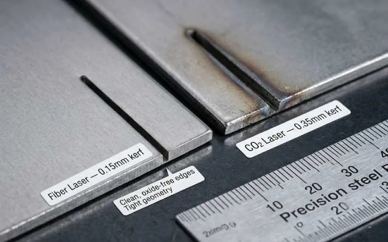
According to Wikipedia’s laser cutting reference, industrial laser cutters achieve positioning accuracy of 10 micrometers and repeatability of 5 micrometers. I want to be clear about what that means: that’s the motion system’s precision — the servo drive and linear rail — not the cut edge. The motion system can position a 0.2mm kerf beam to within 10µm. That doesn’t make your 0.15mm slot come out clean. These are two different specifications, and conflating them in a sales conversation will generate returns.
For electronics OEM work — 0.1–0.3mm vent holes in aluminum housings, micro-slots in stainless brackets, fine geometry in copper bus bars — fiber laser is the baseline requirement. CO2 cannot reach those feature sizes reliably. Ultrafast lasers (picosecond and femtosecond pulse systems) open the sub-0.1mm window for thin metal foils below 0.2mm, but at significantly higher per-hour operating cost. Ultrafast belongs in medical devices and semiconductor applications, not general sheet metal OEM production.
2. Beam Spot Size and Focal Length
Shorter focal length lenses produce smaller beam spots and finer minimum features. A 63.5mm focal length lens focuses tighter than a 125mm lens. The trade-off is depth of field — shorter focal lengths have less tolerance for material surface variation.
I’ve seen this trade-off bite a system integrator configuring a high-precision electronics line. They specified 63.5mm lenses for sub-0.3mm features, achieved the geometry in qualification runs, then watched first-article acceptance fail because their customer’s 1500mm aluminum sheets had ±0.4mm flatness variation. The beam went out of focus mid-sheet. What was 0.15mm kerf at center became 0.28mm at the edges — and the minimum features either burned or failed optical inspection.
Laser Focus World’s analysis of fine laser cutting confirms that laser cutting can focus to approximately 25 microns — roughly one-quarter the width of a human hair — but achieving that in production requires consistent material surface, focus head height, and assist gas pressure across the entire cut. Specify focal length and material flatness tolerance together, not independently.
3. Material Type and Thickness
Minimum feature size scales directly with material thickness. The thicker the material, the wider the kerf, and the larger your minimum feature must be to cut cleanly. Here are the numbers I actually use when reviewing customer application drawings:
| Material | Thickness | Fiber Laser Kerf | Min Hole Diameter | Min Slot Width | Tolerance |
|---|---|---|---|---|---|
| Stainless steel | 0.5mm | 0.10–0.15mm | 0.20mm | 0.50mm | ±0.05mm |
| Stainless steel | 3mm | 0.20–0.30mm | 0.45mm | 3.00mm | ±0.10mm |
| Stainless steel | 10mm | 0.35–0.50mm | 0.75mm | 10.00mm | ±0.20mm |
| Aluminum | 1mm | 0.12–0.18mm | 0.27mm | 1.00mm | ±0.08mm |
| Aluminum | 5mm | 0.25–0.40mm | 0.60mm | 5.00mm | ±0.15mm |
| Mild steel | 3mm | 0.15–0.25mm | 0.38mm | 3.00mm | ±0.10mm |
| Mild steel | 12mm | 0.40–0.60mm | 0.90mm | 12.00mm | ±0.30mm |
| Copper / Brass | 1mm | 0.20–0.30mm | 0.45mm | 1.00mm | ±0.10mm |
Values based on fiber laser cutting with nitrogen assist at standard production parameters. Actual kerf varies with machine configuration, lens condition, and gas purity.

Design rule for every OEM customer: minimum hole diameter = 1.5× kerf width; minimum slot width = material thickness. These aren’t conservative estimates — they’re the numbers that hold across a production shift, not just qualification samples.
4. Assist Gas: Nitrogen vs Oxygen vs Air
Assist gas is the variable distributors most consistently underspecify when quoting precision work. It has a direct and measurable effect on kerf width and minimum feature achievability.
| Assist Gas | Kerf Width Effect | Edge Quality | Best For | Min Feature Suitability |
|---|---|---|---|---|
| Nitrogen (N₂ 99.99%) | Narrowest | Clean, oxide-free | Stainless, aluminum, sub-0.5mm features | Excellent |
| Oxygen (O₂) | +15–25% wider | Oxidized, rougher | Thick mild steel (>6mm) | Poor for fine features |
| Compressed air | +15–25% wider | Acceptable | Non-critical mild steel | Acceptable above 1mm |
For any customer targeting features under 0.5mm, nitrogen at 99.99% purity is not optional. Lower-purity nitrogen introduces oxygen contamination, widens the melt pool, and produces oxidized edges that fail surface finish specifications. I specify purity in the commissioning document — not as a recommendation, as a requirement.
The Focus Drift Problem: Why Your Shift-End Parts Fail When Shift-Start Parts Pass
This is the failure mode no datasheet mentions, and the one responsible for the majority of precision complaints I’ve investigated in OEM installations.

During extended cutting runs, the focusing lens absorbs a small fraction of beam energy. Lens temperature rises. Its refractive index shifts. The focal point migrates upward toward the material surface — what’s called axial focal drift. A kerf that started the shift at 0.20mm can swell to 0.35–0.40mm by hour four of a continuous production block, without any alarm triggering and without the operator noticing.
ADHMT’s laser cutting tolerance analysis describes this precisely: “A kerf that was a tight 0.2mm can abruptly swell to 0.4mm, and the melt pool becomes so wide and viscous that the assist gas can no longer clear it effectively.” The result is inconsistent part geometry across a batch — first 200 parts pass, last 200 parts fail, and the customer’s incoming QC finds the problem, not yours.
What this means for OEM buyers: any machine targeting sub-0.4mm features running continuous production shifts needs either active focus compensation or a defined recalibration protocol. At KASU, we build a 15-minute warm-up cycle and a focus check every four hours using a dedicated test piece into the production standard operating procedure. That single protocol change eliminated focus drift as a reject driver in every installation where we implemented it.
The ISO 9013 Reality Check
ISO 9013 is the governing standard for thermal cutting quality. It evaluates laser cutting on dimensional tolerance, perpendicularity, and surface roughness — and it accounts for material surface waviness compounding with cut edge deviation.
The standard’s perpendicularity measurement isn’t just edge squareness. It blends the plate’s inherent flatness variation with the cut’s angular deviation over the full cut length. A machine achieving ±0.1mm at the cut point can still fail ISO 9013 class tolerance on a wavy plate, because the standard is measuring real-world output, not ideal-condition spec.
When a customer’s RFQ references ISO 9013 compliance, verify that the machine’s stated tolerance is achievable on the customer’s actual material — not polished test samples from the manufacturer’s showroom floor.
Minimum Feature Size by Application: The Matrix That Closes Deals
| Industry Segment | Typical Min Feature | Recommended Laser | Assist Gas | Target Tolerance | Key Risk |
|---|---|---|---|---|---|
| Electronics enclosures | 0.15–0.40mm | Fiber 1–3kW | N₂ 99.99% | ±0.05–0.10mm | Focus drift at volume |
| Medical device components | 0.05–0.20mm | Ultrafast fiber | N₂ 99.99% | ±0.025mm | HAZ on bio-materials |
| Automotive sheet metal | 0.5–2.0mm | Fiber 3–6kW | O₂ or N₂ | ±0.10–0.25mm | Material batch variation |
| HVAC and structural | 1.0–3.0mm | Fiber 3–12kW | O₂ or air | ±0.20–0.50mm | Dross on thick cuts |
| Jewelry / decorative metal | 0.3–0.8mm | Fiber 500W–1kW | N₂ | ±0.05–0.10mm | Surface finish consistency |
| PCB / flex circuits | 0.10–0.30mm | UV or pico fiber | N₂ | ±0.025–0.05mm | Substrate delamination |
The global laser cutting machine market reached $5.94 billion in 2023, expanding at 7.6% CAGR through 2032 — driven primarily by electronics and automotive. These are exactly the segments where minimum feature size specs are most demanding and where distributors who speak fluently about precision limits win over competitors who quote only wattage.
What Distributors and System Integrators Actually Need to Know
I’ll say this plainly: precision is a system output, not a machine feature. A distributor who understands that wins technical deals. One who quotes the datasheet number and moves on generates warranty disputes.
Here’s how to translate precision specs into distributor sales logic that holds up after installation:
Match laser power to material range, then check kerf at the thin end.
A 6kW fiber laser cuts 20mm steel — but if that same customer ever runs 0.8mm stainless with identical machine settings, they’ll see kerf widths approaching 0.25mm and significant heat-affected zones. Wide power modulation range matters more than peak power for mixed-thickness OEM work.
Minimum feature size changes the consumable cost calculation.
Fine-feature cutting demands more frequent lens inspection, tighter nozzle tolerances, and higher-purity nitrogen supply. For an OEM running 16-hour shifts, that’s a real cost delta. Industry analysis indicates hidden operating costs represent 60–80% of a machine’s lifetime expense — build it into your TCO model before the customer builds it into a complaint.
TCO Delta: Standard Precision vs Fine Precision Configuration
| Cost Category | Standard Precision (±0.25mm) | Fine Precision (±0.10mm) | Annual Delta |
|---|---|---|---|
| Machine premium | Baseline | +$15,000–$40,000 | Amortized over 7 years |
| Nitrogen gas (99.99% vs 99.5%) | ~$8,000/year | ~$14,000/year | +$6,000/year |
| Lens inspection/replacement | Every 1,000 hrs | Every 500 hrs | +$3,000–$6,000/year |
| Focus calibration time | Monthly | Weekly | +$2,000/year labor |
| Reject rate delta | ~3–5% | ~0.5–1.5% | -$12,000–$30,000/year saved |
Figures are approximate ranges based on typical OEM production environments. Actual costs vary by shift pattern, material mix, and gas supply contract.
The reject rate saving alone — fiber lasers maintain kerf widths 65% narrower than plasma cutting, with thermal distortion limited to 0.08mm/m in stainless — typically offsets the nitrogen premium and consumable cost delta within 18 months for any customer running over 200,000 parts per year.
Kerf width is a yield spec for expensive materials.
A 0.10mm wider kerf across a dense electronics nest of 500 parts per sheet compounds into meaningful raw material loss. For customers cutting titanium, beryllium copper, or medical-grade stainless, calculate the kerf spec as a yield spec — not just a geometry spec.
Know the red flags in datasheets.
If a machine spec lists positional accuracy ±0.01mm without specifying material, thickness, ambient temperature, or duty cycle — treat it as a lab measurement. ACCURL’s precision analysis confirms fiber laser cutters can achieve tolerances as tight as ±0.003 inches under controlled conditions. Production environments don’t look like controlled conditions. The gap between those two numbers is your customer’s reject rate.
MOQ and lead time implications for precision work.
Sub-0.3mm feature work requires setup validation cuts, parameter calibration per material batch, and tighter preventive maintenance intervals. When quoting MOQ pricing on precision miniature parts, the first 20–50 pieces of any new geometry run are qualification pieces, not production output. That’s a lead time conversation, not a capacity one — and having it before order placement prevents the “why is my first batch late?” call.
How KASU Configures Fiber Lasers for Sub-0.5mm Production Work
At KASU, minimum feature size is a commissioning checklist, not a brochure number. When we configure a KASU fiber laser system for OEM clients targeting sub-0.5mm geometry, the process covers five non-negotiable checkpoints:
Beam quality verification (M² measurement). An M² value below 1.2 is the threshold for fine-feature work. Higher M² means the beam is less focused — minimum feature size degrades accordingly. We document M² at commissioning and include it in the machine handover report.
Focal length selection per application. For features under 0.3mm, we default to 63.5mm focal length lenses and specify tighter material flatness requirements to the customer as a paired specification — not an optional note.
Nitrogen purity specification. 99.99% N₂ minimum for sub-0.5mm work. This goes in the commissioning document as a requirement, not a recommendation. Lower purity widens the melt pool and oxidizes edges.
Focus drift protocol. On systems running extended production, a 15-minute warm-up cycle and focus calibration check every four hours using a test piece. This catches drift before it reaches the production batch.
Per-batch parameter sets. Material thickness varies by up to ±5% from nominal even on certified sheet. Generic material presets don’t absorb that variation. Per-batch parameter sets do.
If you’re evaluating KASU laser cutting tolerance specifications for OEM distribution and want to understand how our systems perform under production conditions — not lab conditions — the engineering team reviews customer application drawings directly.
Frequently Asked Questions
What is the smallest hole a laser cutter can cut?
A fiber laser cuts holes as small as 0.1mm in materials under 1mm thick with nitrogen assist and a 63.5mm focal length lens. In standard industrial production at volume, 0.2–0.3mm is the reliable minimum. Ultrafast lasers reach below 0.05mm for medical and semiconductor applications where throughput is secondary to precision.
What is the minimum kerf width for a fiber laser?
Fiber laser kerf ranges from 0.10–0.15mm on thin materials under optimized conditions. On 1–3mm steel in typical production, expect 0.15–0.25mm. On 10mm steel, expect 0.35–0.50mm. SendCutSend confirms fiber laser beam diameters of 0.006″–0.010″ (0.15–0.25mm) — consistent with production benchmarks.
How small can a CO2 laser cut?
CO2 lasers produce a minimum kerf of 0.20–0.40mm, putting their reliable minimum feature size at 0.40–0.80mm in metal. For any application requiring features under 0.5mm in metal, CO2 is the wrong technology. CO2 remains appropriate for thick acrylic, wood, and non-metallic materials where fine metal precision isn’t required.
What is the minimum hole size for laser cutting in stainless steel?
In 1mm stainless steel with a fiber laser and nitrogen assist, minimum hole diameter is approximately 0.20–0.25mm under optimized conditions, and 0.30–0.40mm for consistent production quality. In 3mm stainless, the practical minimum rises to 0.45–0.60mm. These numbers assume proper focus calibration and consistent gas purity.
Can CO2 lasers match fiber laser precision for small features?
No. CO2’s longer wavelength physically limits its minimum beam spot size. The kerf difference between CO2 and fiber is not a settings issue — it’s a physics constraint. For features under 0.5mm in metal, fiber laser is the only viable standard production option.
What material achieves sub-0.5mm features most reliably?
Thin stainless steel (0.5–1.5mm) with nitrogen assist is the most reliable choice. Its lower thermal conductivity versus aluminum limits heat spread from the kerf. Aluminum’s high thermal conductivity and reflectivity require tighter parameter control to achieve equivalent precision.
How does material thickness affect minimum feature size?
Directly and proportionally. Every additional millimeter of thickness increases kerf width by approximately 0.02–0.05mm. A 0.3mm feature achievable in 1mm stainless requires 0.5mm clearance in 3mm stainless and 0.8mm in 6mm. Design for thickness, not only for geometry.
What ISO standard governs laser cutting tolerances?
ISO 9013 covers thermal cutting — including laser — for materials up to 32mm thick. It evaluates dimensional tolerance, perpendicularity, and surface roughness under real production conditions, not lab conditions. When your customer’s quality engineers reference ISO 9013 in incoming inspection protocols, verify the machine’s tolerance is achievable on their actual material, not the manufacturer’s test samples.
The Specification Gap That Decides Profitability
The machine’s minimum feature size number is the starting point. The question that actually determines whether your customer’s production runs profitably is this: what’s the smallest feature this machine holds reliably across a full production shift, on this material, at this volume?
That number is always larger than the datasheet. The gap between them is filled by thermal drift, material batch variation, consumable degradation, and operator variables. Understanding that gap — and communicating it clearly before equipment selection — separates distributors who close one deal from those who build a five-year customer.
Laser cutters don’t have a single minimum feature size. They have a minimum feature size system. Every component of that system needs to be configured correctly before the spec on paper becomes the result on the floor.

Get the Number Your Production Actually Needs
Send us your customer’s part drawing, material specification, and production volume target. The KASU engineering team returns a written parameter recommendation and tolerance expectation document — specific to your customer’s application — within 48 hours, before equipment selection, before the purchase order.
No generic brochure. No demo room demonstration. A technical document your customer’s engineering team can review, challenge, and approve.
Submit an application drawing for review at KASU and get a precision specification built on production reality, not ideal conditions.